1. VPN (Virtual Private Network)

  ㅇ 공중망(주로,인터넷)을 통해 가상으로 구현된(확장시킨) 사설 네트워크
     - 공중망을 마치 확장된 전용 사설망 처럼 사용
        . 공중망을 통해 사적인 트래픽을 비교적 안전하게 통과시키게 됨


2. VPN 특징

  ㅇ 기존의 공중망을 통한 가상망 구성 가능
     - 유연한 통신망 조정/관리
     - 통신망 주문생산 형태 제공 가능

  ㅇ 망 구축 및 운용의 경제성
     - 전용회선(L/L)에 의한 사설망 구성 보다 구축비용이 저렴하고 복잡함 해소

  ㅇ 자유로운 사적인 주소지정 또는 번호계획 가능

  ㅇ 응용 및 구현 방식/방법이 대단히 많음
     - PBX (PSTN에 의한 VPN 구현)
     - IP-PBX (인터넷에 의한 PSTN용 VPN 구현)
     - IP-VPN (인터넷 VPN) (★) 등


3. VPN 구현방식 구분

  ㅇ 일반적 구분
     - 방화벽 기반의 VPN
        . 응용계층 기반 VPN
     - 라우터 기반의 VPN
        . 네트워크계층 기반 VPN
     - 전용선 기반의 VPN
        . 물리계층 기반 VPN

  ㅇ 시스템 관점 구분
     - 가입자 기반 VPN (CE-VPN, Customer Edge based VPN)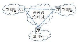
     - 네트워크 기반 VPN (PE-VPN, Provider Edge based VPN)
        . 때론, PP-VPN (Provider Provisioned VPN) 이라고도 함
           .. 주로, ISP 등 망사업자 측이 제공/운용/관리하는 방식의 VPN을 말함
        . 2계층 VPN (2-NBVPN, 2-PEVPN)
        . 3계층 VPN (3-NBVPN, 3-PEVPN)

  ㅇ 서비스 관점 구분
     - VLL (Virtual Leased Lines) 서비스
        . 각 CE 라우터 간의 점대점 연결에 의한 사설망 구성 방식
     - VPRN (Virtual Private Routed Netword) 서비스
        . 공중망에서 ISP의 3계층 라우터 간에 터널링 방식으로 패킷을 전달시킴
     - VPDN (Virtual Private Dial Network) 서비스
        . 원격사용자들이 공중망을 이용하여 원격터미널 형식을 빌어 사용
     - VPRS (Virtual Private LAN Segment) 서비스
        . ISP Edge 라우터들을 이용하여 가상 사설 LAN을 구성


4. VPN 구축시 고려사항

  ㅇ 상호운용성
  ㅇ 확장성
  ㅇ 가용성
  ㅇ 성능
  ㅇ 보안성
http://www.ktword.co.kr/test/view/view.php?nav=2&no=342&sh=l3vpn
VPN
VPN Virtual Private Network 가상 사설망(2021-09-22)
www.ktword.co.kr
L3 VPN의 주요 개념
- Layer 3 기반 네트워크:
- L3 VPN IP 라우팅을 기반으로 하여, 서로 다른 네트워크를 연결합니다. 각 지점은 고유의 IP 주소 체계를 가지고 있으며, L3 VPN을 통해 이들 네트워크 간의 통신이 가능해집니다.
- VPN 서비스 제공자 역할:
- 망사업자: 고객의 네트워크를 연결하고 트래픽을 관리하여 안정적인 통신을 보장합니다.
- 보안 및 프라이버시:
- L3 VPN은 공용 인터넷을 통해 데이터를 전송하면서도, 암호화를 통해 데이터의 보안과 프라이버시를 유지합니다.
L3 VPN 서비스 구성 요소
- CE (Customer Edge) 라우터:
- 고객의 네트워크 경계에 위치한 라우터로, 고객의 내부 네트워크와 VPN을 연결합니다.
- PE (Provider Edge) 라우터:
- 서비스 제공자의 네트워크 경계에 위치한 라우터로, 고객의 CE 라우터와 연결되어 VPN 서비스를 제공합니다.
- P (Provider) 라우터:
- 서비스 제공자의 백본 네트워크를 구성하는 라우터로, PE 라우터 간의 트래픽을 전달합니다.
- VRF (Virtual Routing and Forwarding):
- 각 고객의 라우팅 정보를 분리하여 저장하고 처리하는 기술입니다. 하나의 PE 라우터에서 여러 VRF를 사용하여 여러 고객의 네트워크를 동시에 처리할 수 있습니다.
L3 VPN의 작동 방식
- 라우팅 정보 교환:
- CE 라우터는 PE 라우터와 BGP(Border Gateway Protocol)를 통해 라우팅 정보를 교환합니다. 이를 통해 각 지 점의 네트워크 경로가 PE 라우터에 전달됩니다.
- VRF 설정:
- PE 라우터는 각 고객별로 VRF를 생성하고, 해당 VRF에 라우팅 정보를 저장합니다. 이를 통해 각 고객의 네트워크가 분리되어 관리됩니다.
- MPLS (Multiprotocol Label Switching) 네트워크:
- PE 라우터 간의 트래픽은 MPLS 네트워크를 통해 전달됩니다. MPLS는 데이터 패킷에 레이블을 붙여 빠르고 효율적으로 전달합니다.
- 데이터 전송:
- 한 지점에서 다른 지점으로 데이터가 전송될 때, PE 라우터는 해당 VRF를 사용하여 데이터를 올바른 경로로 전달합니다. MPLS 네트워크를 통해 데이터가 안전하고 빠르게 전달됩니다.
예시를 통한 이해
예시: 회사 B는 서울, 부산, 그리고 대전에 각각 사무실이 있습니다. 회사 B는 세 사무실을 하나의 네트워크로 연결하고 싶어 합니다.
- CE 라우터 설정:
- 각 사무실에 CE 라우터를 설치하고, 이 라우터들을 PE 라우터와 연결합니다. 서울 사무실의 CE 라우터는 서울의 PE 라우터와, 부산 사무실의 CE 라우터는 부산의 PE 라우터와 연결됩니다.
- 라우팅 정보 교환:
- 각 CE 라우터는 BGP를 통해 PE 라우터에 라우팅 정보를 전달합니다. 서울 사무실의 네트워크 경로가 서울의 PE 라우터에 저장됩니다.
- VRF 생성:
- PE 라우터는 각 사무실에 대해 VRF를 생성하고, 해당 VRF에 각 사무실의 라우팅 정보를 저장합니다.
- 데이터 전송:
- 서울 사무실에서 부산 사무실로 데이터를 전송할 때, 서울의 PE 라우터는 해당 데이터를 MPLS 네트워크를 통해 부산의 PE 라우터로 전달합니다. 부산의 PE 라우터는 데이터를 부산 사무실의 CE 라우터로 전달합니다.
이를 통해 회사 B는 서울, 부산, 대전에 있는 사무실을 하나의 네트워크처럼 사용할 수 있게 됩니다. 각 사무실 간의 데이터 전송은 안전하고 빠르게 이루어지며, 서비스 제공자는 네트워크 품질을 관리하여 안정적인 통신을 보장합니다.
What is a Layer 3 MPLS VPN and why to use it?
Layer 3, or VPRN (virtual private routed network), utilizes layer 3 VRF (VPN/virtual routing and forwarding) to segment routing tables for each customer utilizing the service. The customer peers with the service provider router and the two exchange routes, which are placed into a routing table specific to the customer. Multiprotocol BGP (MP-BGP) is required in the cloud to utilize the service, which increases complexity of design and implementation. L3 VPNs are typically not deployed on utility networks due to their complexity; however, a L3 VPN could be used to route traffic between corporate or datacenter locations.
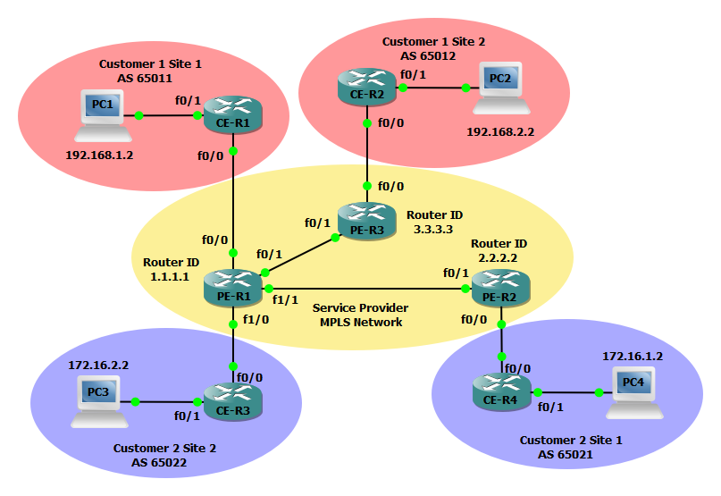
In the example below we will configure three MPLS service provider routers (PEs), two routers for customer 1 (CE), and two additional routers for Customer 2 (CE). The service provider MPLS network will run a basic OSPF configuration and all customer routers will participate in BGP to reach their other sites. Both customer 1 and customer 2 must be provisioned a VRF instance to facilitate a virtual private network across the MPLS cloud.
레이어 3 MPLS VPN은 무엇이며 이를 사용하는 이유는 무엇입니까?
레이어 3 또는 VPRN(가상 사설 라우팅 네트워크)은 레이어 3 VRF(VPN/가상 라우팅 및 전달)를 활용하여 서비스를 이용하는 각 고객에 대한 라우팅 테이블을 분할합니다. 고객은 서비스 제공업체 라우터와 고객별 라우팅 테이블에 배치된 두 개의 교환 경로를 살펴봅니다. 클라우드에서 서비스를 활용하려면 MP-BGP(멀티 프로토콜 BGP)가 필요하므로 설계 및 구현이 복잡해집니다. L3 VPN은 일반적으로 복잡성으로 인해 유틸리티 네트워크에 배포되지 않습니다. 그러나 L3 VPN을 사용하여 회사 또는 데이터 센터 위치 간에 트래픽을 라우팅 할 수 있습니다.
아래 예에서는 MPLS 서비스 공급자 라우터(PE) 3개, 고객 1(CE)용 라우터 2개, 고객 2(CE)용 추가 라우터 2개를 구성합니다. 서비스 제공업체 MPLS 네트워크는 기본 OSPF 구성을 실행하며 모든 고객 라우터는 BGP에 참여하여 다른 사이트에 연결됩니다. MPLS 클라우드 전반에서 가상 사설망을 활성화하려면 고객 1과 고객 2 모두 VRF 인스턴스를 프로비저닝해야 합니다.
Steps to configure a Layer 3 MPLS VPN
Step 1: Configure PE-R1, PE-R2, and PE-R3 interfaces and OSPF to establish basic connectivity. We will also create a loopback interface to serve as as the router-id for the OSPF process and LDP and configure the applicable interfaces for dynamic MPLS forwarding.
레이어 3 MPLS VPN을 구성하는 단계
1단계: PE-R1, PE-R2, PE-R3 인터페이스와 OSPF를 구성하여 기본 연결을 설정합니다. 또한 OSPF 프로세스 및 LDP에 대한 라우터 ID 역할을 할 루프백 인터페이스를 생성하고 동적 MPLS 전달에 적용 가능한 인터페이스를 구성합니다.
PE-R1(config)#interface Loopback0
PE-R1(config-if)#ip address 1.1.1.1 255.255.255.255
!
PE-R1(config)#interface FastEthernet0/1
PE-R1(config-if)#ip address 13.13.13.1 255.255.255.252
PE-R1(config-if)#mpls ip
!
PE-R1(config)#interface FastEthernet1/1
PE-R1(config-if)#ip address 23.23.23.2 255.255.255.252
PE-R1(config-if)#mpls ip
!
PE-R1(config)#router ospf 100
PE-R1(config-router)#router-id 1.1.1.1
PE-R1(config-router)#network 1.1.1.1 0.0.0.0 area 0
PE-R1(config-router)#network 13.13.13.0 0.0.0.3 area 0
PE-R1(config-router)#network 23.23.23.0 0.0.0.3 area 0
PE-R2(config)#interface Loopback0
PE-R2(config-if)#ip address 2.2.2.2 255.255.255.255
!
PE-R2(config)#interface FastEthernet0/1
PE-R2(config-if)#ip address 23.23.23.1 255.255.255.252
PE-R2(config-if)#mpls ip
!
PE-R2(config)#router ospf 100
PE-R2(config)#router-id 2.2.2.2
PE-R2(config)#network 2.2.2.2 0.0.0.0 area 0
PE-R2(config)#network 23.23.23.0 0.0.0.3 area 0PE-R3(config)#interface Loopback0
PE-R3(config-if)#ip address 3.3.3.3 255.255.255.255
!
PE-R3(config)#interface FastEthernet0/1
PE-R3(config-if)#ip address 13.13.13.2 255.255.255.252
PE-R3(config-if)#mpls ip
!
PE-R3(config)#router ospf 100
PE-R3(config-router)#router-id 3.3.3.3
PE-R3(config-router)#network 3.3.3.3 0.0.0.0 area 0
PE-R3(config-router)#network 13.13.13.0 0.0.0.3 area 0
Step 2: Forcibly change the LDP router id on PE-R1, PE-R2, and PE-R3.
2단계: PE-R1, PE-R2, PE-R3의 LDP 라우터 ID를 강제로 변경합니다.
PE-R1(config)#mpls ldp router-id Loopback0 forcePE-R2(config)#mpls ldp router-id Loopback0 forcePE-R3(config)#mpls ldp router-id Loopback0 force
Step 3: Configure vrf vpn-101 for Customer 1 on PE-R1 and vrf vpn-102 for Customer 2 PE-R3 and PE-R1 and PE-R2. We will also enable the VRF on the applicable interfaces and configure an IP address on the interfaces as well.
3단계: PE-R1에서 고객 1에 대해 vrf vpn-101을 구성하고 고객 2 PE-R3, PE-R1 및 PE-R2에 대해 vrf vpn-102를 구성합니다. 또한 해당 인터페이스에서 VRF를 활성화하고 인터페이스에서도 IP 주소를 구성합니다.
PE-R1(config)#ip vrf vpn-101
PE-R1(config-vrf)#rd 65000:101
PE-R1(config-vrf)#route-target export 65000:101
PE-R1(config-vrf)#route-target import 65000:101
!
PE-R1(config)#ip vrf vpn-102
PE-R1(config-vrf)#rd 65000:102
PE-R1(config-vrf)#route-target export 65000:102
PE-R1(config-vrf)#route-target import 65000:102
!
PE-R1(config)#interface FastEthernet0/0
PE-R1(config-if)#ip vrf forwarding vpn-101
PE-R1(config-if)#ip address 10.1.0.1 255.255.255.252
!
PE-R1(config)#interface FastEthernet1/0
PE-R1(config-if)#ip vrf forwarding vpn-102
PE-R1(config-if)#ip address 10.3.0.1 255.255.255.0
PE-R2(config)#ip vrf vpn-102
PE-R2(config-vrf)#rd 65000:102
PE-R2(config-vrf)#route-target export 65000:102
PE-R2(config-vrf)#route-target import 65000:102
!
PE-R2(config)#interface FastEthernet0/0
PE-R2(config-if)#ip vrf forwarding vpn-102
PE-R2(config-if)#ip address 10.4.0.1 255.255.255.0PE-R3(config)#ip vrf vpn-101
PE-R3(config-vrf)#rd 65000:101
PE-R3(config-vrf)#route-target export 65000:101
PE-R3(config-vrf)#route-target import 65000:101
!
PE-R3(config)#interface FastEthernet0/0
PE-R3(config-if)#ip vrf forwarding vpn-101
PE-R3(config-if)#ip address 10.2.0.1 255.255.255.252
Step 4: Next configure a BGP process on PE-R1, PE-R2, and PE-R3 to facilitate advertisements of customer networks over the MPLS network.
4단계: 다음으로 PE-R1, PE-R2 및 PE-R3에 BGP 프로세스를 구성하여 MPLS 네트워크를 통한 고객 네트워크 알림을 용이하게 합니다.
PE-R1(config)#router bgp 65000
PE-R1(config-router)#bgp log-neighbor-changes
PE-R1(config-router)#neighbor 2.2.2.2 remote-as 65000
PE-R1(config-router)#neighbor 2.2.2.2 update-source Loopback0
PE-R1(config-router)#neighbor 3.3.3.3 remote-as 65000
PE-R1(config-router)#neighbor 3.3.3.3 update-source Loopback0
!
PE-R1(config-router)#address-family vpnv4
PE-R1(config-router-af)#neighbor 2.2.2.2 activate
PE-R1(config-router-af)#neighbor 2.2.2.2 send-community extended
PE-R1(config-router-af)#neighbor 3.3.3.3 activate
PE-R1(config-router-af)#neighbor 3.3.3.3 send-community extended
!
PE-R1(config-router)#address-family ipv4 vrf vpn-101
PE-R1(config-router-af)#redistribute connected
PE-R1(config-router-af)#neighbor 10.1.0.2 remote-as 65011
PE-R1(config-router-af)#neighbor 10.1.0.2 activate
!
PE-R1(config-router)#address-family ipv4 vrf vpn-102
PE-R1(config-router-af)#redistribute connected
PE-R1(config-router-af)#neighbor 10.3.0.2 remote-as 65022
PE-R1(config-router-af)#neighbor 10.3.0.2 activate
PE-R2(config)#router bgp 65000
PE-R2(config-router)#bgp log-neighbor-changes
PE-R2(config-router)#neighbor 1.1.1.1 remote-as 65000
PE-R2(config-router)#neighbor 1.1.1.1 update-source Loopback0
!
PE-R2(config-router)#address-family vpnv4
PE-R2(config-router-af)#neighbor 1.1.1.1 activate
PE-R2(config-router-af)#neighbor 1.1.1.1 send-community extended
!
PE-R2(config-router)#address-family ipv4 vrf vpn-102
PE-R2(config-router-af)#redistribute connected
PE-R2(config-router-af)#neighbor 10.4.0.2 remote-as 65021
PE-R2(config-router-af)#neighbor 10.4.0.2 activatePE-R3(config)#router bgp 65000
PE-R3(config-router)#bgp log-neighbor-changes
PE-R3(config-router)#neighbor 1.1.1.1 remote-as 65000
PE-R3(config-router)#neighbor 1.1.1.1 update-source Loopback0
!
PE-R3(config-router)#address-family vpnv4
PE-R3(config-router-af)#neighbor 1.1.1.1 activate
PE-R3(config-router-af)#neighbor 1.1.1.1 send-community extended
!
PE-R3(config-router)#address-family ipv4 vrf vpn-101
PE-R3(config-router-af)#redistribute connected
PE-R3(config-router-af)#neighbor 10.2.0.2 remote-as 65012
PE-R3(config-router-af)#neighbor 10.2.0.2 activateSteps to configure Customer 1 CE devices
Step 5: Configure Customer 1 CE-R1 and CE-R2 with a basic configuration and make use of BGP for dynamic routing.
고객 1 CE 장치를 구성하는 단계
5단계: 기본 구성으로 고객 1 CE-R1 및 CE-R2를 구성하고 동적 라우팅을 위해 BGP를 사용합니다.
CE-R1(config)#interface FastEthernet0/0
CE-R1(config-if)#ip address 10.1.0.2 255.255.255.252
!
CE-R1(config-if)#interface FastEthernet0/1
CE-R1(config-if)#ip address 192.168.1.1 255.255.255.0
!
CE-R1(config-if)#router bgp 65011
CE-R1(config-router)#bgp log-neighbor-changes
CE-R1(config-router)#network 10.1.0.0 mask 255.255.255.252
CE-R1(config-router)#network 192.168.1.0
CE-R1(config-router)#neighbor 10.1.0.1 remote-as 65000
CE-R2(config)#interface FastEthernet0/0
CE-R2(config-if)#ip address 10.2.0.2 255.255.255.252
!
CE-R2(config-if)#interface FastEthernet0/1
CE-R2(config-if)#ip address 192.168.2.1 255.255.255.0
!
CE-R2(config-if)#router bgp 65012
CE-R2(config-router)#bgp log-neighbor-changes
CE-R2(config-router)#network 10.2.0.0 mask 255.255.255.252
CE-R2(config-router)#network 192.168.2.0
CE-R2(config-router)#neighbor 10.2.0.1 remote-as 65000Steps to configure Customer 2 CE devices
Step 7: Configure Customer 1 CE-R1 and CE-R2 with a basic configuration and make use of BGP for dynamic routing.
고객 2 CE 장치를 구성하는 단계
7단계: 기본 구성으로 고객 1 CE-R1 및 CE-R2를 구성하고 동적 라우팅을 위해 BGP를 사용합니다.
CE-R3(config)#interface FastEthernet0/0
CE-R3(config-if)#ip address 10.3.0.2 255.255.255.0
!
CE-R3(config-if)#interface FastEthernet0/1
CE-R3(config-if)#ip address 172.16.2.1 255.255.255.0
!
CE-R3(config-if)#router bgp 65022
CE-R3(config-router)#bgp log-neighbor-changes
CE-R3(config-router)#network 10.3.0.0 mask 255.255.255.0
CE-R3(config-router)#network 172.16.2.0 mask 255.255.255.0
CE-R3(config-router)#neighbor 10.3.0.1 remote-as 65000
CE-R4(config)#interface FastEthernet0/0
CE-R4(config-if)#ip address 10.4.0.2 255.255.255.0
!
CE-R4(config-if)#interface FastEthernet0/1
CE-R4(config-if)#ip address 172.16.1.1 255.255.255.0
!
CE-R4(config-if)#router bgp 65021
CE-R4(config-router)#bgp log-neighbor-changes
CE-R4(config-router)#network 10.4.0.0 mask 255.255.255.0
CE-R4(config-router)#network 172.16.1.0 mask 255.255.255.0
CE-R4(config-router)#neighbor 10.4.0.1 remote-as 65000Verify the configuration
Now that the configuration is finished lets verify our neighbors and routes. Using the show ip bgp vpnv4 all command you can verify the BGP routes distributed and to which VRF they belong.
구성 확인
이제 구성이 완료되었으므로 이웃과 경로를 확인하겠습니다. show ip bgp vpnv4 all 명령을 사용하면 배포된 BGP 경로와 해당 경로가 속한 VRF를 확인할 수 있습니다.

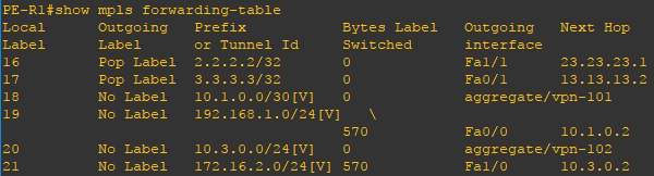
Using the show mpls forwarding-table command you can verify the mpls topology.
show mpls 전달 테이블 명령을 사용하면 mpls 토폴로지를 확인할 수 있습니다.
http://vtechie.com/2014/09/13/mpls-layer-3-vpn/
Configuring Layer 3 MPLS VPN
Load balancing with BGP is not possible in a multihomed environment with two ISPs. BGP selects only the single best path to a destination among the BGP paths that are learned from different ASs, which Read more…
vtechie.com
'Network tech > VPN(L2, L3)' 카테고리의 다른 글
| [Virtual Tech] VLAN vs (VPLS vs E-pipe) vs VPRN (0) | 2024.11.20 |
|---|---|
| [VPN] VPLS와 VPRN 서비스 아키텍처 (2) | 2024.11.18 |
| [L2VPN] L2VPN(Layer 2 Virtual Private Network)은 무엇인가?? (0) | 2024.05.18 |
| [VPN] VPN(가상 사설망, Virtual Private Network)은 무엇인가? (2) | 2024.05.16 |
| [VPN] VPN(Virtual Private Network), 가상 사설 망 (0) | 2023.06.02 |


