
L2 VPN (Layer 2 Virtual Private Network)은 기업이 서로 다른 지역에 위치한 사무실이나 지점을 마치 하나의 로컬 네트워크에 연결된 것처럼 사용할 수 있게 해주는 네트워크 서비스입니다. 이 포스팅에서는 L2 VPN의 주요 개념과 작동 방식을 쉽게 설명하겠습니다.
L2 VPN의 주요 개념

- VLAN 스위치 연결 경험:
- 사용자의 입장: L2 VPN을 사용하면 사용자는 마치 하나의 VLAN 스위치에 연결된 것처럼 보입니다. 이는 서로 다른 지점에 있는 장치들이 같은 네트워크에서 직접 통신하는 것처럼 작동합니다.
- 서비스 품질 제어:
- 망사업자(서비스 제공자): 네트워크 트래픽을 관리하기 위해 Policing (트래픽 규제)와 Shaping (트래픽 모양 조정) 기술을 사용합니다. 이를 통해 각 서비스의 품질을 보장합니다.
- 다중 사이트 서비스 제공:
- 망사업자: IP/MPLS 네트워크를 이용하여 동시에 여러 사이트에 서비스를 제공할 수 있습니다.
- MAC Learning:
- 망사업자 장비: MAC 주소를 학습하여 데이터 프레임을 올바른 경로로 전달합니다.

L2 VPN 서비스 구성 요소
- SDP (Service Distribution Point):
- 역할: 서비스 에지 라우터에 도달하는 방법을 나타냅니다.
- "Far-end": 목적지를 지정하기 위해 시스템 IP를 사용합니다.
- Encapsulation Type: GRE 또는 MPLS를 사용합니다.
- Service Binding: 하나의 SDP에 여러 개의 서비스를 바인딩할 수 있습니다.
- VC Label 생성 및 배포: T-LDP가 활성화된 SDP에 바인딩될 때 VC-Label을 생성하여 배포합니다.
- SDP-ID: 한 장비에서 사용되는 SDP를 고유하게 식별합니다.
- SAP (Service Access Point):
- 정의: 서비스 단말과 연결된 논리적 포트입니다.
- LDP Session:
- 역할: PE 시스템 주소로 사용할 VC Label을 배포합니다.


IP/MPLS VPN 서비스망 구성
IP/MPLS VPN 서비스망은 서비스 제공자와 사용자의 네트워크 장비로 구성됩니다.
- PE (Provider Edge) 라우터:
- 역할: 사용자의 CE 라우터와 연결되어 서비스를 제공하는 장비입니다.
- 기능: 고객 트래픽을 수용하고, IP/MPLS 네트워크에 통합합니다.
- P (Provider) 라우터:
- 역할: 서비스 제공자의 백본 네트워크를 구성하는 장비입니다.
- 기능: 네트워크 백본을 통해 트래픽을 라우팅 하고 전달합니다.
- CE (Customer Edge) 라우터:
- 역할: 고객의 네트워크에 위치한 장비로, PE 라우터와 연결됩니다.
- 기능: 사용자의 로컬 네트워크 트래픽을 서비스 제공자의 VPN망에 전달합니다.
What is a Layer 2 MPLS VPN and why to use it?
Layer 2 VPNs are a type of Virtual Private Network (VPN) that uses MPLS labels to transport data. The communication occurs between routers that are known as Provider Edge routers (PEs), as they sit on the edge of the provider's network, next to the customer's network. Internet providers who have an existing Layer 2 network may choose to use these VPNs instead of the other common MPLS VPN, Layer 3. Layer 2 VPNs uses the Label Distribution Protocol (LDP) to communicate between PE routers and established a virtual circuit providing the customer one or more private point-to-point connection.
In the example below we will configure three MPLS service provider routers (PEs), two routers for customer 1 (CE), and two additional routers for Customer 2 (CE). The service provider MPLS network will run a basic OSPF configuration and all customer routers will simply use static routers to point to their other sites. Both customer 1 and customer 2 must be provisioned a private virtual circuit to facilitate a direct point-to-point connection. Using CDP both customer routers should appear directly connected.
레이어 2 MPLS VPN은 무엇이며 이를 사용하는 이유는 무엇입니까?
레이어 2 VPN은 MPLS 레이블을 사용하여 데이터를 전송하는 VPN(가상 사설망) 유형입니다. 통신은 공급자 네트워크 가장자리, 고객 네트워크 옆에 있는 공급자 에지 라우터(PE)라고 알려진 라우터 간에 발생합니다. 기존 레이어 2 네트워크를 보유한 인터넷 제공업체는 다른 일반적인 MPLS VPN인 레이어 3 대신 이러한 VPN을 사용하도록 선택할 수 있습니다. 레이어 2 VPN은 LDP(레이블 배포 프로토콜)를 사용하여 PE 라우터 간에 통신하고 고객에게 제공되는 가상 회선을 설정합니다.
아래 예시에서는 MPLS 서비스 공급자 라우터(PE) 3개, 고객 1(CE)용 라우터 2개, 고객 2(CE)용 추가 라우터 2개를 구성합니다. 서비스 제공업체 MPLS 네트워크는 기본 OSPF 구성을 실행하며 모든 고객 라우터는 단순히 정적 라우터를 사용하여 다른 사이트를 가리킵니다. 직접 지점 간 연결을 용이하게 하려면 고객 1과 고객 2 모두 개인 가상 회선을 프로비저닝해야 합니다. CDP를 사용하면 두 고객 라우터 모두 직접 연결된 것으로 나타나야 합니다.

Steps to configure a Layer 2 MPLS VPN
Step 1: Configure PE-R1, PE-R2, and PE-R3 interfaces and OSPF to establish basic connectivity. We will also create a loopback interface to serve as as the router-id for the OSPF process and LDP.
레이어 2 MPLS VPN을 구성하는 단계
1단계: PE-R1, PE-R2, PE-R3 인터페이스와 OSPF를 구성하여 기본 연결을 설정합니다. 또한 OSPF 프로세스 및 LDP에 대한 라우터 ID 역할을 하는 루프백 인터페이스를 생성합니다.
PE-R1(config)#interface Loopback0
PE-R1(config-if)#ip address 1.1.1.1 255.255.255.255
!
PE-R1(config)#interface FastEthernet0/1
PE-R1(config-if)#ip address 13.13.13.1 255.255.255.252
!
PE-R1(config)#router ospf 101
PE-R1(config-router)#router-id 1.1.1.1
PE-R1(config-router)#network 1.1.1.1 0.0.0.0 area 0
PE-R1(config-router)#network 13.13.13.0 0.0.0.3 area 0
PE-R2(config)#interface Loopback0
PE-R2(config-if)#ip address 2.2.2.2 255.255.255.255
!
PE-R2(config)#interface FastEthernet0/1
PE-R2(config-if)#ip address 23.23.23.1 255.255.255.252
!
PE-R2(config)#router ospf 101
PE-R2(config-router)#router-id 2.2.2.2
PE-R2(config-router)#network 2.2.2.2 0.0.0.0 area 0
PE-R2(config-router)#network 23.23.23.0 0.0.0.3 area 0PE-R3(config)#interface Loopback0
PE-R3(config-if)#ip address 3.3.3.3 255.255.255.255
!
PE-R3(config)#interface FastEthernet1/0
PE-R3(config-if)#ip address 13.13.13.2 255.255.255.252
!
PE-R3(config)#interface FastEthernet1/1
PE-R3(config-if)#ip address 23.23.23.2 255.255.255.252
!
PE-R3(config)#router ospf 101
PE-R3(config-router)#router-id 3.3.3.3
PE-R3(config-router)#network 3.3.3.3 0.0.0.0 area 0
PE-R3(config-router)#network 13.13.13.0 0.0.0.3 area 0
Step 2: Forcibly change the LDP router id on PE-R1, PE-R2, and PE-R3.
2단계: PE-R1, PE-R2, PE-R3의 LDP 라우터 ID를 강제로 변경합니다.
PE-R1(config)#mpls ldp router-id Loopback0 forcePE-R2(config)#mpls ldp router-id Loopback0 forcePE-R3(config)#mpls ldp router-id Loopback0 force
Step 3: Configure a pseudowire-class and configure dynamic MPLS between PE devices on PE-R1, PE-R2, and PE-R3.
3단계: pseudowire 클래스를 구성하고 PE-R1, PE-R2 및 PE-R3의 PE 장치 간에 동적 MPLS를 구성합니다.
PE-R1(config-if)#interface FastEthernet0/1
PE-R1(config-if)#mpls ip
!
PE-R1(config)#pseudowire-class ETHERNET
PE-R1(config-pw-class)#encapsulation mpls
PE-R2(config)#pseudowire-class ETHERNET
PE-R2(config-pw-class)#encapsulation mpls
!
PE-R2(config-if)#interface FastEthernet0/1
PE-R2(config-if)#mpls ipPE-R3(config)#pseudowire-class ETHERNET
PE-R3(config-pw-class)#encapsulation mpls
!
PE-R3(config)#interface FastEthernet1/0
PE-R3(config-if)#mpls ip
!
PE-R3(config)#interface FastEthernet1/1
PE-R3(config-if)#mpls ip
Step 4: Configure virtual circuits 101 and 102 to provide a private point-to-point for Customer 1 and Customer 2. The virtual circuit 101 is for Customer 1 and 102 is for Customer 2. The xconnect command followed by the IP address of the peer router will establish the connection for the local interface into the private virtual circuit.
4단계: 고객 1과 고객 2에 개인 지점 간을 제공하도록 가상 회로 101과 102를 구성합니다. 가상 회로 101은 고객 1을 위한 것이고 102는 고객 2를 위한 것입니다. xconnect 명령 뒤에는 고객의 IP 주소가 옵니다. 피어 라우터는 로컬 인터페이스에 대한 연결을 개인 가상 회로에 설정합니다.
PE-R1(config)#interface FastEthernet0/0
PE-R1(config-if)#duplex full
PE-R1(config-if)#xconnect 3.3.3.3 101 pw-class ETHERNET
!
PE-R1(config)#interface FastEthernet1/0
PE-R1(config-if)#duplex full
PE-R1(config-if)#xconnect 2.2.2.2 102 pw-class ETHERNET
PE-R2(config)#interface FastEthernet0/0
PE-R2(config-if)#duplex full
PE-R2(config-if)#xconnect 1.1.1.1 102 pw-class ETHERNETPE-R3(config)#interface FastEthernet0/0
PE-R3(config-if)#duplex full
PE-R3(config-if)#xconnect 1.1.1.1 101 pw-class ETHERNETSteps to configure Customer 1 CE devices
Step 5: Configure Customer 1 CE-R1 and CE-R2 with a basic configuration. Each router will have a single static route directing all unknown traffic to the adjacent site router.
고객 1 CE 장치를 구성하는 단계
5단계: 기본 구성으로 고객 1 CE-R1 및 CE-R2를 구성합니다. 각 라우터에는 알 수 없는 모든 트래픽을 인접한 사이트 라우터로 전달하는 단일 고정 경로가 있습니다.
CE-R1(config)#interface FastEthernet0/0
CE-R1(config-if)#ip address 10.1.0.1 255.255.255.252
!
CE-R1(config)#interface FastEthernet0/1
CE-R1(config-if)#ip address 192.168.1.1 255.255.255.0
!
CE-R1(config)#ip route 0.0.0.0 0.0.0.0 10.1.0.2
CE-R2(config)#interface FastEthernet0/0
CE-R2(config-if)#ip address 10.1.0.2 255.255.255.252
!
CE-R2(config)#interface FastEthernet0/1
CE-R2(config-if)#ip address 192.168.2.1 255.255.255.0
!
CE-R2(config)#ip route 0.0.0.0 0.0.0.0 10.1.0.1Steps to configure Customer 2 CE devices
Step 6: Configure Customer 2 CE-R3 and CE-R4 with a basic configuration. Each router will again have a single static route directing all unknown traffic to the adjacent site router.
고객 2 CE 장치를 구성하는 단계
6단계: 기본 구성으로 고객 2 CE-R3 및 CE-R4를 구성합니다. 각 라우터에는 알 수 없는 모든 트래픽을 인접한 사이트 라우터로 전달하는 단일 고정 경로가 다시 있습니다.
CE-R3(config-if)#ip address 10.2.0.2 255.255.255.252
!
CE-R3(config)#interface FastEthernet0/1
CE-R3(config-if)#ip address 172.16.2.1 255.255.255.0
!
CE-R3(config)#ip route 0.0.0.0 0.0.0.0 10.2.0.1
CE-R4(config)#interface FastEthernet0/0
CE-R4(config-if)#ip address 10.2.0.1 255.255.255.252
!
CE-R4(config)#interface FastEthernet0/1
CE-R4(config-if)#ip address 172.16.1.1 255.255.255.0
!
CE-R4(config)#ip route 0.0.0.0 0.0.0.0 10.2.0.2Verify the configuration
Now that the configuration is finished lets verify our neighbors and routes. Using the show cdp neighbors, show mpls forwarding-table, and show mpls l2transport vc # commands you can verify the MPLS deployment. Use the ping command to verify connectivity from PC1 to PC2 from PC3 to PC4. In Customer 1 Site 1 issue the show cdp neighbors command to verify CE-R2 appears directly connected.
구성 확인
이제 구성이 완료되었으므로 이웃과 경로를 확인하겠습니다. show cdp neighbor , show mpls Forwarding-table 및 show mpls l2transport vc # 명령을 사용하여 MPLS 배포를 확인할 수 있습니다. ping 명령을 사용하여 PC1에서 PC2, PC3에서 PC4로의 연결을 확인합니다. 고객 1 사이트 1에서 show cdp neighbor 명령을 실행하여 CE-R2가 직접 연결된 것으로 나타나는지 확인합니다.

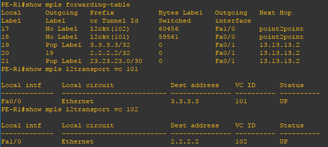
Use the show mpls forwarding-table to verify the virtual circuits on PE-R1, PE-R2, and PE-R3. Using the show mpls l2transport vc 101 and show mpls l2transport vc 102 commands you can verify the local interface participating in the virtual circuit and the destination where the virtual circuit is terminated. You can repeat on the other provider routers to verify the virtual configuration end to end.
PE-R1, PE-R2 및 PE-R3의 가상 회선을 확인하려면 show mpls 전달 테이블을 사용하십시오 . show mpls l2transport vc 101 및 show mpls l2transport vc 102 명령을 사용하면 가상 회선에 참여하는 로컬 인터페이스와 가상 회선이 종료되는 대상을 확인할 수 있습니다. 다른 공급자 라우터에서 반복하여 가상 구성을 종단 간 확인할 수 있습니다.
http://vtechie.com/2017/04/12/mpls-layer-2-vpn/
Configuring Layer 2 MPLS VPN
Load balancing with BGP is not possible in a multihomed environment with two ISPs. BGP selects only the single best path to a destination among the BGP paths that are learned from different ASs, which Read more…
vtechie.com
'Network tech > VPN(L2, L3)' 카테고리의 다른 글
| [Virtual Tech] VLAN vs (VPLS vs E-pipe) vs VPRN (0) | 2024.11.20 |
|---|---|
| [VPN] VPLS와 VPRN 서비스 아키텍처 (2) | 2024.11.18 |
| [L3VPN] L3VPN(Layer 3 Virtual Private Network)은 무엇인가? (0) | 2024.05.18 |
| [VPN] VPN(가상 사설망, Virtual Private Network)은 무엇인가? (2) | 2024.05.16 |
| [VPN] VPN(Virtual Private Network), 가상 사설 망 (0) | 2023.06.02 |


